
How do I understand an undocumented PLC program I inherited?
The engineer who wrote it is gone, the comments were never written, and the machine still has to run. A working order for inherited PLC programs, and what AI can trace for you.
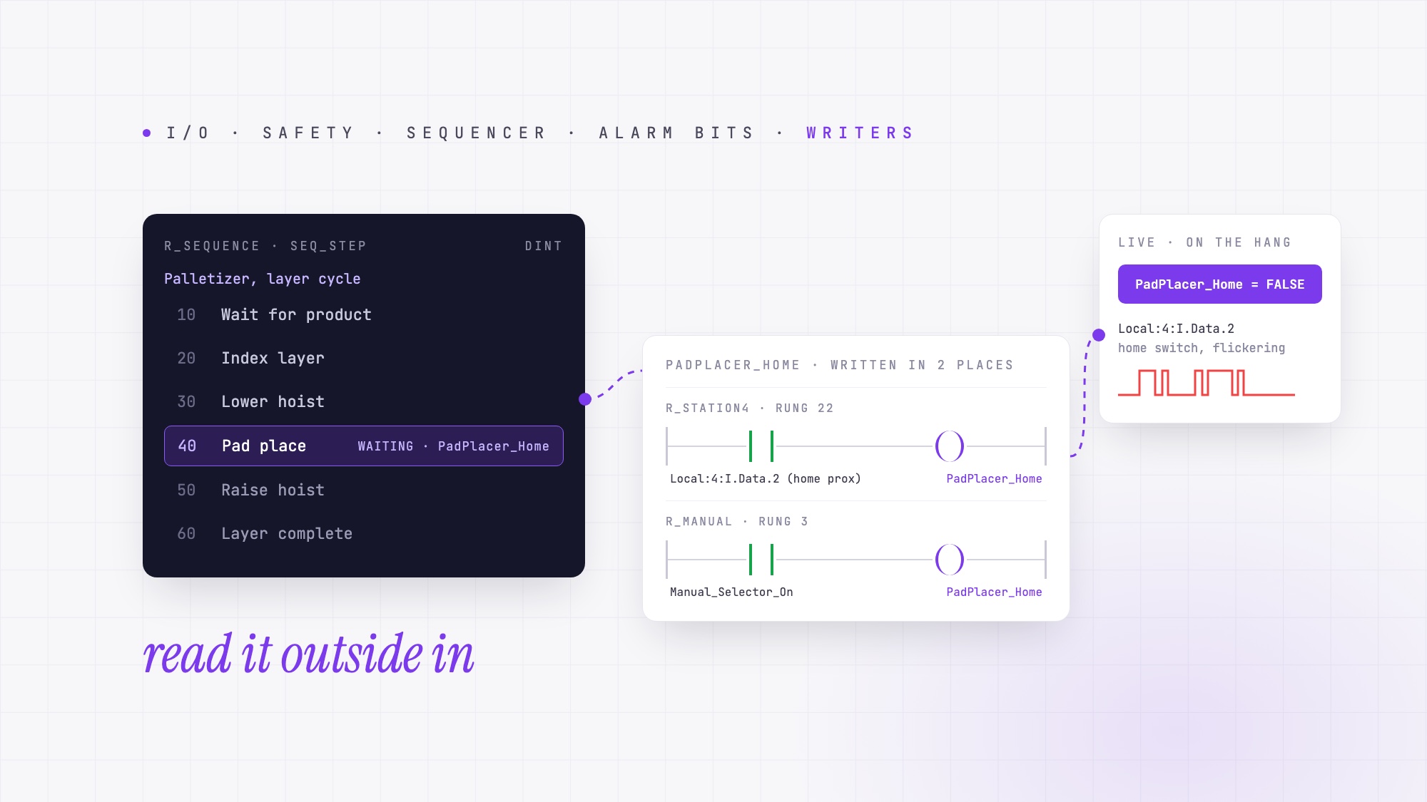
Work from the outside in. Map the I/O to the physical machine first, then find the safety chain, then the sequencer that drives the machine through its steps, then trace the alarm bits backward. Do not read rung 1 to rung 3,000. Those four passes give you a map of the machine and a starting point for each fault.
What is the right order to read an inherited PLC program?
Outside in. Start with the hardware configuration and whatever drawings you have. Match the addresses to physical devices as you confirm them. Even a partial I/O map makes the logic easier to read. Then find the safety-related signals, the sequencer and the alarms before reading any routine end to end.
Start with backups of the controller, HMI and drive configurations, and work from copies. Before observing a live cycle, have authorized personnel review the controller’s force status under the site’s procedures. Leave forces, bits and the running program as you found them.
| Step | What you look for | How you find it by hand | What AI can help trace |
|---|---|---|---|
| 1. Map the I/O | What every input and output is physically | Hardware configuration plus the electrical drawings; label each address as you confirm it | Finds references to configured I/O points in the project so you can use confirmed device names in your notes |
| 2. Find the safety chain | E-stops, guard doors, safety relay feedback, the master control relay | Find the safety task or the status signals returned by external safety hardware, then trace how the standard logic uses them | Shows where safety-related permissives are used and which branches affect them in the supplied logic |
| 3. Find the sequencer | The integer or bit array that steps the machine (Step 10 idle, 20 clamp, 30 extend) | Look for repeated comparisons and writes to the same step register or set of step bits | Traces the transitions it finds and drafts step names from the outputs and exit conditions |
| 4. Trace the alarm bits backward | The coil behind each HMI alarm text | Cross-reference the alarm bit; the rung that sets it lists the conditions the last programmer considered a fault | Traces the alarm bit to its setting logic. Matching it to display text requires the HMI configuration, and tracing an upstream permissive requires the upstream controller project |
| 5. Check for alternate paths and multiple writers | Manual overrides, conditional routine calls and tags written in more than one place | Cross-reference the tags and review when each routine runs | Finds writers and branches to review in the project |
| 6. Use the HMI as documentation | What the operator names things | Open the HMI project; a button that writes B3:0/5 to start a motor just told you what B3:0/5 is | With a screenshot of the HMI screen attached, it can compare what the screen shows with live tag values |
| 7. Watch it run | Which bits change at each step | Trends and watch lists grouped by station, while the machine runs a cycle; the eight-step PLC troubleshooting method is the ordered version | With live tag access, helps compare current values against the conditions found in the project |
A worked example: a palletizer nobody can explain
Consider a CompactLogix palletizer that stops between layers about once a shift. The operators press reset to get it moving again. Most tags are raw I/O aliases such as Local:3:I.Data.7, and the routine comments are sparse. This is an illustrative example, not a customer case.
The order of work above, applied:
| Step | What the program showed |
|---|---|
| I/O map | Local:3:I.Data.7 is wired to the layer-pad photoeye on the drawings; recorded as PE_LayerPad_Present in the I/O map |
| Safety chain | The reviewed logic uses ESTOP_Chain_OK, Guard_Door_1_Closed and Guard_Door_2_Closed as permissives for MCR_OK |
| Sequencer | Seq_Step (DINT) in R_Sequence: 10 Wait for product, 20 Index layer, 30 Lower hoist, 40 Pad place, 50 Raise hoist, 60 Layer complete. The hang is always with Seq_Step = 40 |
| Alarm bits | HMI “Pad placer timeout” is Alm_PadTimeout, set in R_Alarms rung 9 when Seq_Step = 40 for longer than T_PadPlace.PRE (8 s) without PadPlacer_Home going true |
| Alternate paths and multiple writers | PadPlacer_Home is written in two places: R_Station4 rung 22 from the home proximity switch, and R_Manual rung 3, which sets it when the manual selector is on |
| HMI | The HMI “Pad Reset” button writes HMI_PadReset, which jumps Seq_Step to 50. That is what the operators have been pressing |
| Watch it run | On the hang, PadPlacer_Home is false while the placer is physically home. The home switch Local:4:I.Data.2 flickers; the mount is loose |
The project points you to the right signal. It shows that step 40 waits for PadPlacer_Home, that two routines write that bit, and that the reset command skips to step 50. Live observation shows the home input flickering. At the machine, the engineer finds the loose switch mount.
That code trace is what AI for PLC troubleshooting can help with. Ask which conditions hold step 40, where each one is written, and what the reset command changes. The answers give you specific signals to verify during the next stop.
Can AI understand an undocumented PLC program?
Yes. A complete export gives AI the context to trace a rung across routines. It can point you to the places that write a bit, show where else the bit is read and connect it to the relevant sequence step. Ask for routine and rung references so you can check the trace in your engineering software.
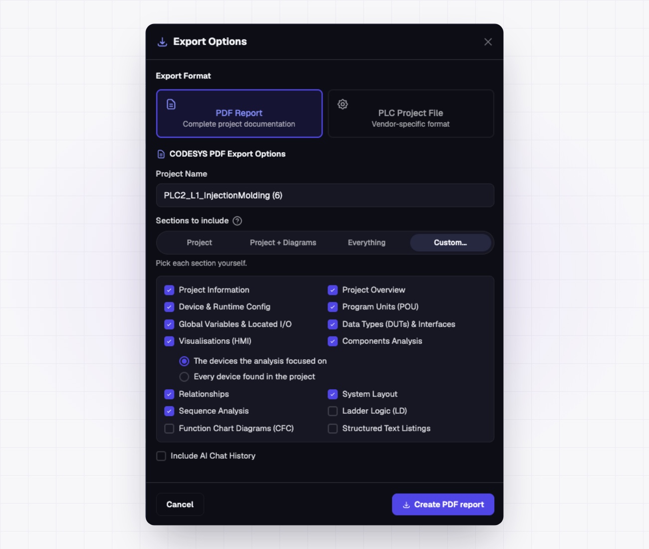
PLCs.ai analyzes supported project exports from Studio 5000, TIA Portal and CODESYS V3, answers “what must be true for this output” with the routines and rungs cited, drafts the tag descriptions and comments that were never written, and, with the Companion App (aka Companion) connected, overlays live tag values so you can see which condition is false now. The output is a draft for an engineer who knows the machine to review; the AI says when a description is inferred from structure rather than proven by the logic. Once reviewed, export it as a PDF report to share with maintenance, hand to the next engineer or keep on file, so the next person who inherits the machine does not start from zero. See the three-PLC injection-molding cell example for a project analysis in practice.
How do you stop the next engineer from inheriting the same problem?
A program becomes undocumented because what people learn about it stays with them: in one engineer’s notes, in a maintenance technician’s memory, in a file on someone’s laptop. Documenting it once does not fix that if the result ends up in the same place.
An AI assistant inside one engineer’s IDE, or a copilot that helps one user at a time, has the same weakness. What it explains and drafts stays with the person who asked, and the next engineer starts over.
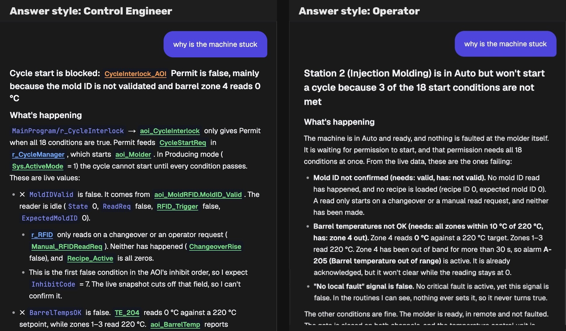
PLCs.ai is a shared platform, not a single-user assistant. Automation engineers, maintenance and production work from the same project, each getting answers in terms that fit their role (how role-based answers work). What the platform learns about the program is kept in one place and updated with every change and revision, so any documentation anyone generates reflects the current version, not whichever copy last sat on someone’s laptop.
What the program cannot tell you
An offline PLC project describes possible behavior. To establish what the machine actually does, check the rest of the system.
- 01Physical I/O and wiring. Confirm the physical wiring and device condition against the drawings and the machine.
- 02Drive and HMI configuration. VFD parameters, HMI scripts and recipe data change behavior and are not in the PLC file.
- 03Other controllers. A permissive produced by the upstream PLC is a single bit here; its cause is in another project. Line-level tools read both; a single-project tool stops at the boundary.
- 04Safety functions. An AI trace can help locate logic for review. Validation of the safety function and any changes go through your site’s safety process.
Use the gaps in the trace to build your inspection checklist.
Frequently asked questions
How do I reverse-engineer legacy PLC code?
Outside in: map the I/O to the drawings, find the safety chain, find the sequencer, trace alarm bits back to the logic that sets them, then review alternate paths and multiple writers. Use the HMI to confirm operator terminology. Before observing a live cycle, have authorized personnel check force status under site procedures.
Can AI add comments to existing ladder logic?
Yes. Once it has read the whole program it drafts tag descriptions, rung comments that explain intent and routine summaries, marked as inferred where the logic does not prove them, for an engineer to review before they go back into the project. PLCs.ai can also export the reviewed documentation as a PDF report for sharing and record-keeping.
How do I find where a tag is written in a PLC program?
Cross-reference it in the engineering software and look at the destinations, not the sources: a bit may be read in fifty places but is usually written in one. If it has two writers, check when each routine runs and which value reaches the consuming logic. PLCs.ai can help find those references in the supplied project.
What is the difference between an RSLogix 500 and a Studio 5000 inherited program?
RSLogix 500 (SLC 500, MicroLogix) uses file addresses such as B3:0/4 and N7:12, so look for meaning in any available symbols, comments, electrical drawings and HMI labels. Studio 5000 projects have tags, but inherited ones often use raw aliases. The order of work is the same; see AI for legacy PLC code for the migration side.
Is it safe to upload an inherited PLC program to an AI tool?
Yes, with the right tool. PLCs.ai is SOC 2 Type II compliant, never trains on your project files, keeps them separate from every other customer’s data and deletes them on your schedule. Reading an exported project offline does not touch the running machine. Check your organization’s rules for sharing project files, and see the Trust and Security page for the details.
What can AI not see in an inherited PLC program?
Field wiring, drive and HMI configuration, other controllers’ logic unless it has their projects too, and live machine state unless it is connected to the controller. A good tool lists what it could not establish instead of guessing.
How do I keep an inherited PLC program documented after I’ve figured it out?
Keep what you learned where everyone who works on the machine can reach it, and keep it current as the program changes. On PLCs.ai, automation, maintenance and production share one project. Its understanding of the program updates with each revision, so documentation generated at any time reflects the latest version, and you can export it as a PDF report for your records.
More from the blog
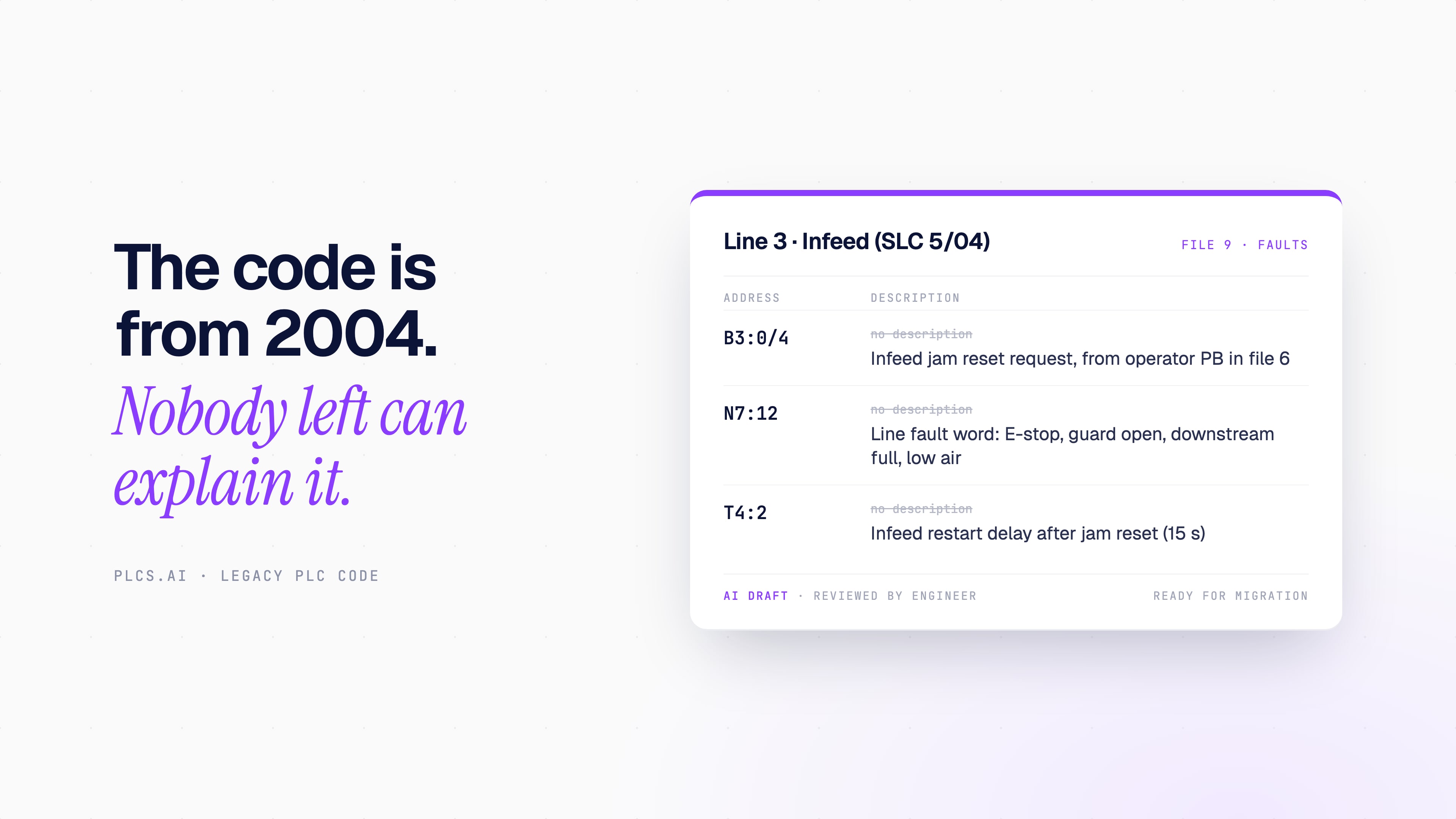
AI for legacy PLC code: understand, document and migrate programs nobody wants to touch
Can AI understand, comment or convert old PLC programs? What it does well on RSLogix 500, PLC-5 and S7-300 code, what the vendor tools still do, and what still needs an engineer.
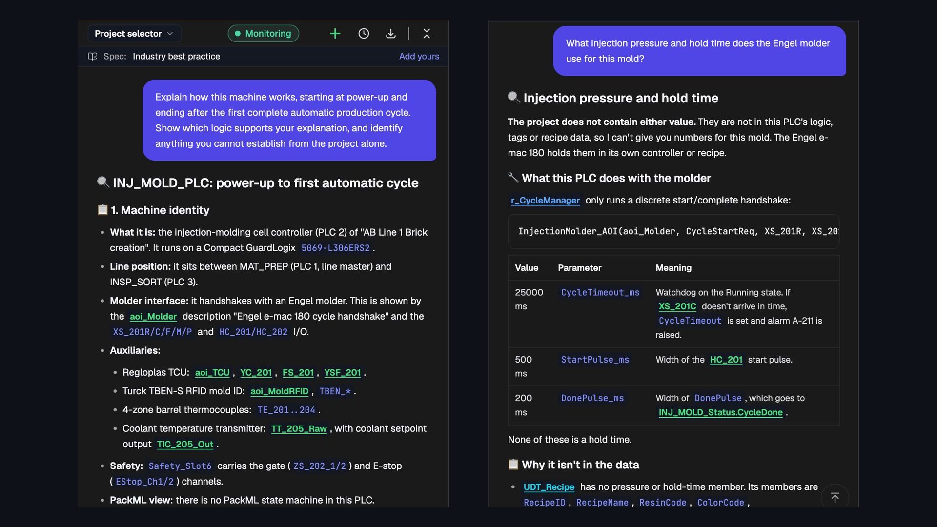
Can AI read an entire PLC project and explain how the machine works?
We asked PLCs.ai to explain an Allen-Bradley injection-molding cell from power-up to its first automatic cycle. What whole-project understanding looks like, and seven ways to test it.
AI PLC Troubleshooting for Maintenance Teams Without the IDE
Most people who need PLC answers never open Studio 5000 or TIA Portal. How role-based AI gives operators and maintenance teams answers they can act on.